I would like to thank my thesis supervisors, Dr.Tech. Jouni Isoaho and Prof. Reino Kurki-Suonio, for their guidance and suggestions during the work. I also use this opportunity to thank my friends Mr. Henrik Herranen and Mr. Janne Salmijärvi for their proofreading and aesthetical consultation.
Tampere, August 1st, 1996
Pasi Ojala
Telkontie 50
39230 Osara
Finland
PASI OJALA: A Pre-emptive Multitasking Operating System
for an Embedded Emulation Tool
Diplomityö: 69 sivua, 29 liitesivua
Tarkastajat: TkT Jouni Isoaho ja Prof. Reino Kurki-Suonio
Rahoittajat: TEKES, NDC, NMP, NCS, Fincitec
Avainsanat: ASIC, FPGA, Käyttöjärjestelmä
Koska nykyisiä digitaalisen signaalinkäsittelyn menetelmiä käytetään innovatiivisilla alueilla, kuten modeemeissa, matkapuhelimissa, televisiossa ja multimediatuotteissa, on näissä käytettyjen algoritmien testaaminen käytännön järjestelmissä usein tarpeen. Laitteistoemulaattorit ovat eräs tapa suunnitteluaikojen lyhentämiseksi.
Projektin päätavoite oli laitteisto-ohjelmisto -yhteissunnitteluun soveltuvan laitteistoemulaattorin suunnittelu ja toteuttaminen. Projektissa suunniteltiin ja toteutettiin laitteistoemulaattori nimeltään BOAR. Oma osani projektista oli käyttöjärjestelmän sekä tarvittavan muun ohjelmiston suunnittelu ja toteutus tälle emulaattorille, sekä emulaattorilaitteiston jatkotestaus.
Tämä diplomityö esittelee lyhyesti käyttöjärjestelmän suunnittelunäkö-kohtia. Lyhyen emulaattorilaitteiston esittelyn jälkeen kerrotaan miten eri mekanismit on tässä käyttöjärjestelmässä toteutettu, sekä perusvalintojen kohdalta miksi niihin on päädytty. Tämän jälkeen käydään läpi käyttöjärjestelmän tarjoamia palveluja. Myös ohjelmistonkehitysympäristöä, muuta systeemiin kirjoitettua ohjelmistoa, kokemuksia projektista sekä jatkokehitysnäkymiä selvitetään.
Tuloksena oli hyvin toimiva ja vakaa käyttöjärjestelmä tarpeellisine sovelluksineen. Automaattisen partitiointityökalun kehittäminen muiden töiden ohella ja ilman lisätutkimusta osoittautui liian kunnianhimoiseksi tavoitteeksi, ja tutkimusta tällä alueella onkin jatkettu.
PASI OJALA: A Pre-emptive Multitasking Operating System
for an Embedded Emulation Tool
Master's Thesis: 69 pages, 29 appendix pages
Supervisors: Dr.Tech. Jouni Isoaho and Prof. Reino Kurki-Suonio
Financed by: TEKES, NDC, NMP, NCS, Fincitec
Keywords: ASIC, FPGA, Operating System
Since today's Digital Signal Processing algorithms are used in innovative application areas, such as modems, mobile telephones, televisions, and multimedia platforms, real-life testing of algorithms is often required. This is done using hardware emulators to reduce the design time.
The main goal in the project was to create a hardware emulator for high-speed software-hardware co-development environment. A hardware emulation tool named BOAR was designed and implemented. My part of the project was to design and implement an operating system (OS) for this emulation tool, and perform additional testing of the hardware. Application programming was also my responsibility.
After a short introduction to some of the design aspects of an operating system, and a description of the actual hardware, this thesis goes through some of the major design decisions that were made. Implemented operating system services are discussed. In addition, the development system and other system software is also glanced at and the development experiences and upcoming activities are revealed.
A well-working and stable operating system and all necessary applications were produced. Developing an automatic partitioning software without further research proved to be too optimistic, and research in this area has been continued.
--------------------------------------------------------------------------
bps              bits per second
embedded system  a computer system not perceived as a computer by the user
ADC              Analog to Digital Converter
ABEL             PAL programming language
ASIC             Application Specific Integrated Circuit
BOAR             Board for Object Animated Reviewing
COFF             Common Object File Format
CPU              Central Processing Unit
DAC              Digital to Analog Converter
DMA              Direct Memory Access
DOS              Disk Operating System
DRAM             Dynamic Random Access Memory
DSP              Digital Signal Processor
EEPROM           Electrically Erasable Programmable Read Only Memory
EPROM            Erasable Programmable Read Only Memory
FPGA             Field Programmable Gate Array
GNU              GNU's not Unix
HTML             Hypertext Markup Language
I/O              Input/Output
NFS              Network File System
OS               Operating System
PAL              Programmable Array Logic
PLA              Programmable Logic Array
RAM              Random Access Memory
PCB              Printed Circuit Board
SIMM             Single Inline Memory Module
ROM              Read Only Memory
RS-232           Asychronous serial communication standard
SCCS             Source Code Control System
SRAM             Static Random Access Memory
VHDL             VHSIC Hardware Description Language
VHSIC            Very High Speed Integrated Circuit
WWW              Worl Wide Web
XNF              Xilinx Netlist Format
--------------------------------------------------------------------------
ASICs are designed to be used for a specific purpose by a single company. The logic capacity, functionality and speed can be optimized for the application. However, ASICs often have too high starting costs to be used for prototyping. Unlike ASICs, field programmable gate arrays (FPGAs) are configured by the user, which results in a fast manufacturing turn-around and low re-programming costs. This explains why FPGAs have gained popularity as prototyping tools.
The goals of ASIC hardware emulators [15], which consist of programmable logic (FPGAs), control logic and software, are to reduce the design time and increase the probability of the first turn success and also provide an environment for rapid prototyping, where both hardware and software can be developed and tested together. Existing hardware emulators [8] are mainly targeted to be general purpose tools and to support a wide range of ASIC architectures. However, emulating the design at full speed is a requirement that may not be achieved without a specialized emulator.
The main goal in the project was to create a hardware emulator for high-speed software-hardware co-development environment. In digital signal processing applications the ASIC architecture is usually dataflow-oriented. A signal goes through a fixed path, each block between the system input and output doing a specific operation. To provide an emulation environment for these kinds of signal processing applications, a dataflow-oriented approach was used.
A hardware emulation tool named BOAR [2, 3, 12] was designed and implemented in the project. My part of the project was to design and implement an operating system (OS) for this emulation tool, and perform additional testing of the hardware. Application programming was also my responsibility.
BOAR was constructed as two attached printed circuit boards (PCBs). The top board, which is the actual emulation part, has four Xilinx XC4010 FPGA devices [18] (XC4013s and XC4025s can also be used) and two Texas Instruments DSP320C50 DSPs [19] with some memory and expansion connections. The bottom board, which controls the system, has a Motorola MC68302 microprocessor [20, 25], one Xilinx XC4005 FPGA device for clock generation, 256 kilobytes of EPROM memory, 4 megabytes of flash-type EEPROM [21], a National Semiconductor Ethernet Controller [22], memories for test data, and SIMM sockets for 6 megabytes of DRAM for the processor.
Traditionally this kind of hardware emulator system is controlled by a custom-made system software that performs a specific fixed task, or the emulation hardware is totally controlled by a host system. None of the available emulation tools offer a real general-purpose operating system that can be used for various tasks other than emulation. Besides the use of the emulation environment, the operating system created for BOAR opens the system for programmers. Anyone with moderate programming skills can use the system routines to write their own applications. No special knowledge of the hardware is necessary.
This thesis discusses the software development that was done for BOAR. Chapter 2 very briefly introduces the hardware. Chapter 3 discusses general responsibilities and design issues of an operating system. Chapter 4 describes the main services provided by the implemented operating system. Next chapters describe the software development environment and discusses the support libraries and filesystems written for the system. Chapter 8 reveals the development experiences from the project. Future plans are presented in the penultimate chapter. The last chapter draws conclusions of the work.
Operating systems may be divided into groups using several criteria: single-tasking/multi-tasking, single-user/multi-user, non-protected/protected. Multi-tasking systems may be further divided into subgroups: task swapping/co-operative/pre-emptive multitasking.
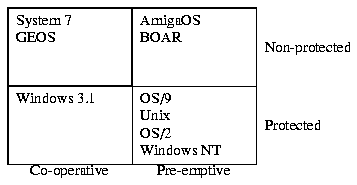
Figure 1 lists some multitasking systems. The differences between co-operative and pre-emptive scheduling and some discussion on protection can be found later in this chapter. For more information about the evolution of operating systems, among other things, see for example [9].
The operating system controls the usage of system resources (memory, processor and peripherals) in such a way that the overall efficiency of the system is maximized. On the other hand, responsiveness must be preserved as much as possible. If one thread of execution (from now on referred to as task or process) is waiting for an event to occur, the execution of another task may be resumed while the task is waiting and no processor time is wasted. That event may be either a physical, external, or a logical event, such as the completion of an operation.
Several approaches to the management of resources are possible. Processor resources can be managed either by the operating system (pre-emptive multitasking) or by the applications themselves (co-operative multitasking). Peripherals can be accessed either directly by the applications or through a device driver, which also works as an abstraction layer. It greatly depends on the intended usage of the system and partly on the preferences of the implementor how far the abstraction is carried.
In a co-operative multitasking system the tasks themselves call an operating system function to change the running task. Here lies the strong and at the same time the weak point of the co-operative system. Because the tasks have to explicitly call the switch function, they must call it often enough to maintain a fair division of processor resources between the tasks. If one task does not voluntarily give up the CPU, it just does not give it up. There is nothing that can be done.
On the other hand, a co-operative system usually wins on task switch times. This is because the tasks are in fairly well defined states each time they call the task switch routine. There is less state information to be stored. On the bare minimum, only the program counter has to be saved, but this would only move the saving of important registers from the operating system to the applications. So, usually some of the registers are saved, and registers that are not preserved are clearly documented. Another win for the co-operative system is that there is no need for any exclusion methods such as semaphores to protect data structures that are used by several tasks.
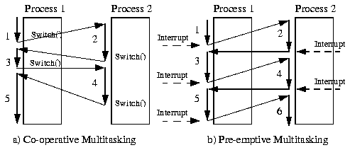
The example in Figure 2 shows the fundamental difference between co-operative and pre-emptive multitasking systems. In co-operative systems the tasks themselves call a function (Switch() in this example) to give away the processor. In pre-emptive systems a timer interrupt causes the task changes. As the example illustrates, processor time is more evenly shared between the tasks in the pre-emptive multitasking system.
This goal obviously contradicts the normal goal of minimizing the response times to user interactions and maximizing the throughput of the system, although in a way they also have common goals.
The scheduling of system resources must be performed according to some well-understood, adaptive algorithms so that the timing behaviour of the system is understandable, predictable, and maintainable. The problem of determining an optimal schedule is known to be NP-hard [17] and is thus impractical for real-time task scheduling. This is why such algorithms must be based on heuristics.
One simplified attempt at a partial solution is the use of priorities. The task completion time requirements are mapped into priorities. The more important a task is (the sooner it has to complete), the higher the assigned priority (the sooner it will be completed). The scheduler only has to execute the highest priority task that is ready to run.
However, this approach loses the information about completion times, and the end result is that the original, required completion times are not necessarily met. Also, this does not work on a heavily loaded system, because the execution of high priority tasks may consume all processing resources. Lower priority tasks that also have their requirements for the latest completion time are not executed at all. There could still be enough resources on the system to satisfy the real-time requirements, but the priority-based scheduling just cannot do it.
The scheduling algorithm is not the only part of the system that must be carefully designed to make a system real-time. Each operating system mechanism a task uses must have a predictable delay. This is not always easy, for example when a high-priority task is communicating with a lower-priority task. If the lower-priority task does not get enough CPU resources, it may never reply. This problem can be reduced by increasing the priority of the lower-priority task until it replies, but this may cause bigger problems than it solves.
In embedded control systems it is very usual that once the operating system and the applications have been coded and tested, the code does not need to be changed at all. It is put into a non-volatile storage device (typically an EPROM) and the product is shipped to the customer. Because the running tasks are known beforehand, selecting co-operative multitasking makes task switching very fast.
As long as you have only well-behaving (well-programmed) applications, and you beforehand know their interactions, co-operative multitasking works quite well. However, if the number of tasks running at any one time is not known, pre-emptive multitasking gives an advantage over co-operative by allowing an application to be coded as if it was the only application running in the system.
Pre-emptive multitasking also allows more flexible software design. This is because in co-operative systems the applications are usually required to consist of a main (event) loop, which calls subroutines to handle the different functions of the process and passes control to other processes within small enough intervals. In pre-emptive systems this is not necessary, although this kind of event-loop-driven architecture is also very convenient for at least filesystem handlers.
The main responsibility for the operating system concerning the emulation itself is to provide a platform for applications that configure the emulation hardware, run the emulation and save the results. To increase the flexibility in the emulation, it should also be possible to use the processor as part of the emulation, for example to generate new test data in real-time.
However, there are systems that do not have hardware support for this kind of full protection nor it is absolutely needed. Because there was no memory management unit in Motorola 68000, which was used in first Amiga model (Amiga 1000), AmigaOS was developed without hardware protections. The same applies to Apple's System 7. On the other hand, the absence of memory management unit in the original operating system has made it very hard to make use of it in the later versions.
More relaxed protections usually allow more efficient implementation, but also create additional things to consider. One of the more efficient things is message passing between processes. Because all tasks share the same address space, message passing can be implemented simply by passing a reference to the message instead of copying the actual messages back and forth. On the other hand, programs must reside in different memory areas if they are to be executed simultaneously. This is one drawback.
If there is a need to load and execute new code dynamically, code and data segments must be relocated before the program can be run. A block of memory is allocated for the program, and the program code and data are copied there. After this all references in the program are corrected to be suitable for the memory location the program now resides in. This may present a problem to overcome if the development environment does not provide tools for the creation of relocatable executables.
Protected environments usually implement operating system calls with software interrupts. Inside the software interrupt handler the operating system determines the requested operation, performs it, and when completed, returns control to the calling process. On some processors the software interrupt mechanism may present considerable overhead.
Software interrupts are not needed for all calls in a system with more relaxed protections. Jump tables with shareable, re-entrant libraries are a general, expandable and easily updatable solution and software interrupts are only used by the operating system itself when needed.
If the operating system knows what resources each task has, it is possible to remove any task at any time and free all the resources it has allocated, including open files. However, keeping track of each and every resource is a big burden on the operating system, especially on a system where the applications are assumed to be well-behaved to begin with. The small overhead of resource tracking may also be unacceptable in a system with little memory. However, tracking of the free memory is almost always a necessity. The only exception is a system where memory is statically allocated for each desired usage beforehand, bu in such a system also multitasking would probably be unnecessary.
The tracking of memory can be implemented in several ways. The memory can be divided into blocks and each block has one bit in an allocation map, which tells if the block is allocated or not. This is very crude, and ends up wasting vast amounts of memory, because only a whole block can be allocated at a time. A better method is to use a list to hold the free memory blocks. Whenever a memory is being allocated, this list is checked for a large enough block and the first match is returned and removed from the free memory list.
This is how most modern operating systems approach memory allocation. Further refinements are possible, for example the free memory blocks can be grouped according to their sizes to speed up the allocation process. Second-level services may also exist, and these try to provide additional features, such as memory pool management (a large memory block is allocated, and several small allocations are then returned from that block).
When allocated memory is freed by an application, the block is inserted into the right position in the free memory list. If the adjacent blocks are also free, they are merged together with the freed block to form the largest possible contiguous block of memory. This keeps the free memory blocks as big as possible at all times.
In a multi-tasking system tasks routinely allocate and de-allocate memory. This may cause some heavy fragmentation in the free memory pool. In virtual-memory systems this problem is moderately easy to circumvent. Each task has its own virtual address space and thus the fragmentation is also restricted inside that virtual address space. However, in other systems that do not use, or even have a memory management unit, fragmentation of memory is a system-wide problem and is to be avoided at any cost.
The most important factor in reducing the fragmentation is the allocation method used. When a task requests a block of memory, the memory allocation routine locates a free memory block that is big enough to satisfy the request. If the free block is bigger than the requested size, the block is split in two, usually causing fragmentation later.
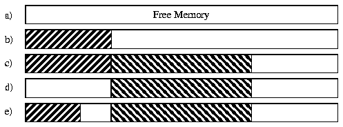
In the example in Figure 3, two blocks of memory are allocated in b) and c). The first allocation is then freed in d) and a new, smaller block allocated in e). The free memory has now been split into two areas. By repeating this procedure we get more memory fragments.
The allocation routine can be written in a way that it returns the smallest available memory block that satisfies the request. It sounds better than taking the first block that is big enough, but this strategy (called "best fit") turns out to actually make fragmentation worse. The problem is that there generally is no exact fit and some words of memory are always left over. A left-over block of this size is too small to be used for anything and by staying in the memory list it ends up slowing down the allocation and de-allocation routines. Also, best fit needs to traverse the whole free memory list to find the best match, first fit can stop when it locates the first suitable block.
In general, just taking the first block that is big enough ("first fit") works, and is not as bad on fragmentation as best fit. However, any general purpose allocation scheme is going to have problems with fragmentation. On the other hand, well-written applications can reduce the problem by making allocations wisely. One good method is to use memory pool management, which was mentioned earlier.
The operating system for BOAR was modelled after the Commodore AmigaOS [6, 23]. However, not everything that is found in AmigaOS was implemented and some of the bad choices in AmigaOS were corrected. The concept of dynamic, shared, re-entrant libraries and the message passing system are the key parts that were strongly influenced by AmigaOS. "Simple is beautiful" is the driving force.
BOAR operating system is not an actual real-time system, just a pre-emptive multitasking system with task priorities. However, this does not mean that the actual hardware emulation subsystem could not be real-time. It is just the interaction between the operating system and the special emulation hardware that may not be real-time.
If MC68302 is used as part of emulation, for example generating or feeding test data, actual real-time operation may be required. In these cases it is possible to avoid those system services that compromise real-time operation and attain the required performance.
Because BOAR does not have hardware support for strict protections, in principle everything in the system is accessible by all processes. However, all processes run in user state, thus limited protection between the operating system and the processes is available. Some of the instructions in the processor's instruction set are not accessible in user state.
Memory allocation routines only track unallocated memory and leave the deallocation to the applications themselves. However, a mechanism to help applications to track their allocations is provided. This approach was taken, because in an embedded system memory should be conserved where possible. Also, omitting the tracking of allocated memory (and other similar resources) makes things simpler.
The core of a pre-emptive operating system consists of a task switching routine, an interrupt handler, and routines to manage the other system resources. The interrupt handler is the key part in a pre-emptive multitasking system, because it decides when it is time to switch tasks. When a task has used its time-slice, voluntarily given up the processor, or it is pre-empted by another task with a higher priority, the switching routine is called. The scheduler [5] then decides which task to run next, and the switching routine loads that task and starts to run it.
There are three states a task can be in: currently running, ready to be run or waiting for a signal. A task is said to "have the CPU" when it is running. When tasks are switched, the task that was running "loses the CPU," while the task that was ready "gets the CPU" ("acquires the CPU") and begins to run. Other transitions between the states are called "goes to sleep" and "wakes up." In BOAR a newly-created task enters in the ready state and a task that has ended its execution leaves the system through the waiting state. Figure 4 shows these task states and transitions between the states.

There are different techniques for the selection of the task to run next. Naturally, complex real-time scheduling algorithms take much more processing time than simple priority-based algorithms.
To make things simpler and faster, BOAR uses a simple priority queue with round-robin algorithm between tasks at the same priority. By default time slices of 100 ms are used, but this may be tuned in 10 ms steps, if needed. If the time slices are too short, some performance is lost because there are more context switches than would be actually needed. If too long time slices are used, response times will suffer. The selected default, 100 ms is a compromise between efficiency and response times.
Round-robin means that all tasks with the same priority get the CPU in turn. Each task that is ready (i.e. not waiting and not currently running) is kept in a task ready list and has a priority attached to it. The elements in the list are sorted according to their priorities (hence the term "priority queue"). Higher priority tasks are put into the head of the list, lower priority tasks are at the tail.
When a new task is being added, it is enqueued to the list, and will be located before all lower priority tasks, but behind all tasks with a higher or the same priority. When the scheduler in the operating system needs a new task to run, it simply takes the first task from the head of the list. This implements priorities and also the round-robin scheduling between all tasks with the same priority.
Because the task ready list is prioritized, no task with a low priority will get the CPU if there is a ready task with a higher priority. This may cause problems in an overloaded system. Lower priority tasks may never get the CPU if one high priority task is at all times running. This is called "starving" and it can be reduced by allowing dynamic priorities. Tasks that use up their time slices get priority demotions and tasks with lower priorities may have a chance to run. Unfortunately, dynamic priorities make the response times unpredictable, because a high priority task does not necessarily get the CPU when it needs to.
When a task goes to sleep it is put into a task wait list. This list does not need to be sorted according to anything. Tasks may be added into the head or to the tail of the list. It is only important what happens when a task wakes up. When a task wakes up, it is removed from the task wait list and enqueued to the task ready list. This ensures that the task will be executed as soon as possible.

The example in Figure 5 shows what happens to the task lists when a task wakes up. The initial state of the task lists are shown in a). Then a task with priority 1 wakes up. In b) the task has been enqueued into proper place in the task ready list.
If the scheduler does not find a ready task to be run (the task ready list is empty), the processor will be stopped until the next interrupt happens. There is a special instruction in the processor for this. When the processor is stopped, power consumption is reduced and the system memory bus is freed. The bus can then be used by another bus master, in this case by the ethernet controller. Because of this, stopping the processor when there is no real work to be done not only decreases power consumption, but also increases system performance.
An interrupt may and will eventually cause a task wakeup. After the interrupt is serviced, the scheduler tries again to locate a ready task. If there is a ready task, it gets the CPU. If the ready list is still empty, the processor is stopped again.
Because the timer interrupt needs to be serviced whether the running task is switched or not, and there may be more state information to be saved and restored in each task switch, a pre-emptive system has a slightly bigger overhead than a co-operative system. On the other hand, the timer interrupt server can also update a system clock and service timer requests. This removes the interrupt service overhead for the task switching part, because the interrupt service routine would have to be called anyway.
Device drivers can be implemented as part of the operating system core, as separate entities, or as something in-between; separate installable and removable objects that are used through the operating system routines. Implementing the drivers as independent modules makes expansion very easy, drivers can even be installed and removed on the fly. This is how device drivers are implemeted in BOAR.
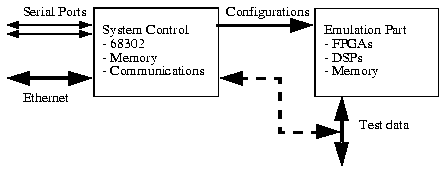
The emulation part handles the actual emulation, system control section handles the communication between the user and the system, sets up the emulation, and optionally routes the results back to the user.
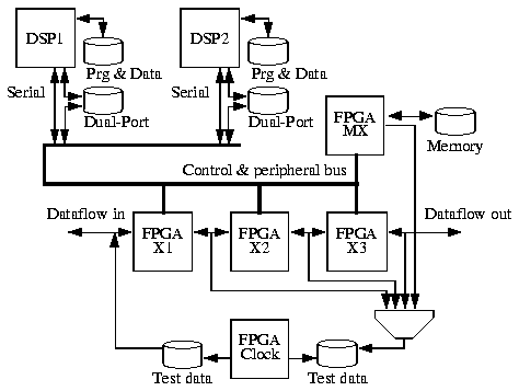
Three of the FPGA devices (dataflow: X1, X2 and X3) are connected in a dataflow-architecture, one (master: MX) is reserved for dataflow control and other tasks. Currently these four FPGA devices are Xilinx XC4010 chips, which provide approximately 10000 gates of theoretical logic capacity each [18]. However, this limit is rarely reached in practice [11]. Bigger-capacity XC4013 and XC4025 chips can be used directly.
A control and peripheral bus is connected to each one of these FPGA chips and also into dual-port memories that can also be accessed by DSPs. These memories provide synchronized communication between DSPs and FPGAs. This means that DSPs can view the FPGA part as a memory-mapped peripheral device. Serial communication between FPGAs and DSPs is also possible. A third dual-port memory (not shown in the picture) is connected between the control and peripheral bus and the MC68302 microprocessor.
If emulation uses any of these resources, the corresponding signals on the control and peripheral bus become reserved and should not be used for anything else. It should be observed that any of these FPGA devices can control these resources.
One smaller FPGA device (clock FPGA), Xilinx XC4005 with approximately 5000 gates of theoretical logic capacity, is used to generate clock signals for the system. It is also used to generate addresses for test data memories, when these memories are used in simulation. User-provided test data is fed into the dataflow and output data can be captured from any of the dataflow outputs, or from the master FPGA. Because test data memories are only 16 bits wide, and the dataflow itself is 40 bits, only a part of the data can be captured. This is not so much of a problem, because DSP320C50 DSPs have 16-bit datapaths, and in most applications 16 bits is enough. If more than 16 bits are needed to the output, multiplexing can be used.

The overall control part is show in Figure 8. One Motorola MC68302 microcontroller, using a 20-MHz clock source, controls the whole system. The controller has access to almost all memories on BOAR. Only the dual-port memories that reside between DSPs and the FPGA part are not accessible. The operating system is in EPROM (256 kilobytes). Flash-type EEPROM (4 megabytes) is used as a non-volatile storage media (a logical disk drive), and DRAM (upto 6 megabytes) provides working memory.
Two serial ports (selectable rates, by default 38400 bps) and thin ethernet (maximum throughput of 10 Mbps) are used to communicate with BOAR. The controller performs FPGA device configurations and DSP program and data loading. The controller also enables or disables the dual-port memories and serial communication channels in the emulation part. This way they do not interfere when they are not used, and more routing signals become available.
The controller also has serial connections to DSPs or FPGAs, and it can communicate with the FPGAs using dual-port memory. Simulation test data is put, by the controller, into the test data memory, from where it can be read by the clock FPGA. Test data memory, DSP 1 memory, and DSP 2 memory are only accessible by the controller when the clock FPGA, DSP 1, and DSP 2 are in reset state, respectively.
A node type which omits the name and priority fields also exists, and is otherwise compatible with the list routines, except for routines using those fields. Using this minimal version of the node structure saves some memory in situations where named and prioritized nodes are not needed.
Lists are heavily used by the system and routines to create, maintain, traverse, and delete lists are also accessible to the application programmer. By using the routines provided by the system the programmer can easily use dynamic structures avoiding artificial limits in his programs.
A mechanism for a task to track its own memory allocations is provided. However, because the tracking involves lists, two longwords (8 bytes) are used for each allocated block.
"First fit" is used in the memory allocating routines. The first large enough block is used when memory is allocated.
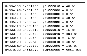
Figure 9 shows that after a while, the free memory list will contain some quite small memory fragments. Allocations are always rounded to the next larger 8-byte block size, so the actual minimum size of an allocation is 8 bytes.
Interrupts can be disabled and enabled by a program if absolutely necessary. This is necessary if one part of the driver software runs as a usual task and another part of it as an interrupt handler. Both parts need to access and change common data structures. Because normally the interrupt handler may get control at any time it is problematic to access the data from the task-part of the handler. By disallowing interrupts the task can access the data safely without danger. Of course it should only disable the interrupts for the shortest possible time, because it directly affects the real-time properties of the system. Also, if interrupts are disabled for too long, a watch-dog-timer external to the controller resets the system.
Usually it is sufficient to only forbid task switching. For example, if many tasks manipulate the same structures this may be needed. Unfortunately this also has an effect on the real-time properties. Better exclusion methods are available by using semaphores. Semaphores only affect those tasks that really access the same structures, not all tasks in the system.
Each task has a priority, which is used to decide which task to run after the current task has used its time slice. In BOAR all higher priority tasks have precedence over lower priority tasks. A simple function can be used to set a new priority at any time. A greater number means higher priority and a smaller number a lower priority. Priority values from -128 (lowest) to 127 (highest) are available. Normally applications run at zero priority. Handlers and other system tasks run at priorities over ten.
Each task also carries an owner identification number, which indicates the owner of the task. This is used for file protection, making it possible for a filesystem to prevent users other than the file owner from accessing a file.
Routines for adding and removing tasks are provided. Each task has a name, which can be used to locate tasks by name. However, because task names are not guaranteed to be unique, many tasks with the same name may be running at the same time.
When a waiting task is signalled by another task or an interrupt handler, and the signal is one of the signals the task is waiting for, the task wakes up and resumes execution. The signal (or signals) that caused the wakeup are reported to the task and the task can then act accordingly. If the task was waiting for multiple signals, the return value is used to decide what to do next.
Signals are not nested. This means that a signal is either set or not set, thus sending a signal that is already set does nothing. When signals are used to indicate messages arriving to a port, there may be more than one message in the port, or no messages at all when the corresponding signal is set. This has to be remembered when dealing with messages.
Eight signal bits are reserved by the operating system, the remaining 24 signal bits can be allocated and freed by the applications.
An action is associated with each message port. That action is performed each time a message arrives to that port. The message is always appended to the message queue independent of the action specified. Three actions are available: either nothing happens, a task specified in the port structure (normally the owner of the port) is signalled, or a software interrupt is generated.
A software interrupt is a convenient feature when creating device drivers, because it also takes care of the exclusion problem. When using software interrupts the interrupt server in the device driver is the only one that needs to write to the data structures. However, message ports that send signals are the only variety that can be created using the system routines.
Message ports can be either public or private. If a port is made public, the port name can be used by other tasks to find the port. Both public and private ports can be created and deleted with exec.library functions. A private port can be turned into a public port if necessary.
Also, there exists a function that waits for a message to arrive to a specific port. This routine must assume that a signal can happen even without a message arriving to the port or several messages may have been arrived when a signal is received. Also, even if the signal is not set, there may be a message in the port.
In BOAR messages are asynchronous. When a message is sent, the sender does not need to wait until the receiver has received or processed the message. Because message passing uses signals, it is possible to wait for messages to arrive to any number of ports. Upto 24 ports can be created with the routine provided by the system, because each port allocates one signal. However, it is possible to use the same signal for several ports, which removes the problem of signal bits running out.
Sometimes synchronous communication is needed. Fortunately, it is trivial to create synchronous message passing using asynchronous messages. Instead of just sending the message to the port the sender will attach a reply port to the message. The sending task then waits for the message to arrive to the reply port after sending the message. The receiver gets the message from its message port, processes the message and sends the message back to the reply port specified in the message. When the original sender receives the reply message, it knows that it is safe to reuse or deallocate the message and can also check the message for any return values.
A mechanism and routines to handle message replies is provided. It can be used in both an asynchronous and a synchronous way. Because waiting for multiple signals is possible, a task can simultaneously wait for a reply and some other event, if necessary.
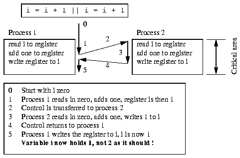
In the example in Figure 10, two processes are updating a common variable i. If the updating process is interrupted in the middle by the other process, the end result will be incorrect. This critical area or code, the updating process, must be executed as an atomic operation, and cannot be interrupted in order to allow it to work correctly.
In BOAR you can forbid task switching or disable interrupts if the shared data structure is written by an interrupt handler. Unfortunately these methods also prevent other tasks that do not access that shared data structure from running. Semaphores add the capability to only exclude the tasks that want to use the structure.
When a task wants to use a semaphore-protected data structure, it must first call a function to gain access rights to the structure. This is called obtaining the semaphore. Access can be either simple reading or both reading and writing. Many readers are allowed to obtain a semaphore simultaneously. However, only one writer can be allowed at any one time in which case no reader or another writer can have or obtain the semaphore.
If one task has obtained the semaphore for writing to the structure, other accesses to the semaphore are queued. When the task releases the semaphore, these queued tasks can obtain the semaphore. If a task wants a write-access it must first wait for all readers or possibly another writer to release their locks on the semaphore.

New shared libraries may be written by the user. The main advantage of a shared dynamic library compared to a link library is that the library code is loaded only once into memory and any number of tasks may use the library simultaneously. With link libraries each task would have the same piece of code linked into them. So, dynamic libraries help to conserve memory, which is one advantage. Another advantage is that when the library is updated, each program using the library gets updated at the same time. With link libraries you would need to relink the programs.
Any number of tasks may execute the library code simultaneously. The library may remove this re-entrancy by using semaphores if this is needed for exclusion or synchronization purposes. Two fixed routines Open and Close are internally used by the exec.library calls OpenLibrary and CloseLibrary. Other library routines are freely definable by the library programmer. All library calls are executed in the calling task's context. At the assembly language level a library call is a register-relative jump to a subroutine with a negative offset value.

The example in Figure 12 shows the library routine calling system. Parameters for the memory allocation routine are first put into registers. The size of the allocation, 200 bytes, is put into the first data register, and allocation flags are set to zero (1). The base address of the library is fetched into the address register, and the program jumps into a subroutine using the library base and the proper negative offset (2). In the next stage the library jump table moves the control to the actual memory allocation routine (3). Control is returned to the program after the allocation routine is finished (4). The return value is put into a memory location called _MemBlock (5).
Parameters are passed in registers for all exec.library functions except semaphore routines. Semaphore routines have been written in C language and because of that it was simpler to just use the stack for parameter passing. Normally the user does not need to know about this, because dynamic libraries are used through link library stub routines. Also, dos.library was fully written in C and it takes its parameters in the stack.
Whenever a program sends a message to a device driver, the BeginIO function gets called, which then takes care of the message. The device driver may choose to implement the service using a software interrupt, in which case it further delivers the message to the right message port. However, the BeginIO function may also service the request immediately. For example, device status queries may be serviced this way, because they usually do not have to modify the device driver's data structures.
The AbortIO function may be used to recall a request that has not been serviced yet. This is needed for asynchronous input and output, where it is often necessary to exit the program before a sent request is serviced. The program does not need to wait for example for a keypress to arrive before it can exit.
The management of these resources is done using public semaphores. An application wanting to use the emulation part locates the dedicated public semaphore and tries to gain write (exclusive) access to that semaphore. Semaphore routines provide queued access to the emulation part. Also, an application can try to obtain the semaphore without queueing. In that case it either gets write access to the semaphore or an error is returned. Normally the execution is suspended until the semaphore becomes free.
If an application only wants to query the state of different signals on the emulation part, read (shared) access to the semaphore is sufficient. Semaphore routines allow any number of read accesses simultaneously and write accesses are automatically queued until all previous readers have released their semaphores.
Currently the whole emulation part is handled as one big resource, and it is accessed by one program only, but it is fairly easy to allow access to the two DSPs and to the FPGA block separately, if required. This makes it possible to have up to three test runs active simultaneously.
---------------------------------------------------
Memory, I/O and Ethernet controller configuration
Start memory refreshes
Memory tests (size/speed)
Initialize the kernel library (exec.library)
Reserve space for the first task
Initialize memory pool
Initialize the first task
Start the timer
Switch to user state
Continue running that task
Initialize other libraries and ROM-resident modules
---------------------------------------------------
MC68302 has four programmable chip select lines. These chip selects must be configured first to make the memory map valid so that all memories can be accessed. Each of the chip selects have a programmable data acknowledge delay for asynchronous data bus operation.
A built-in RISC-style co-processor in the MC68302 is used to handle serial port traffic and dynamic RAM refreshes. Memory refreshes are simple memory reads performed by the co-processor. A starting address, refresh distance and the number of refreshes per loop are defined. After each read from the memory the address counter is increased by the refresh distance. After the defined number of refreshes the start address is loaded into the counter register and the refreshes continue from that address.
Only an external trigger signal is needed and one of the two general purpose timers is used for that. One memory refresh cycle is performed after each timer underflow. Because the timer is configured into continuous count mode and underflows do not generate interrupts, memory refreshes are totally transparent to the processor. After starting the refreshes no further attention is needed. However, about 2 % of the processor memory bandwidth is consumed by the memory refresh cycles.
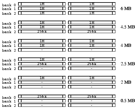
After the memory configuration is set and RAM refreshes are started, the startup routine will check how much RAM there actually is. BOAR has sockets for three 1-megabyte DRAM SIMM pairs. Not all sockets need to be filled. However, the SIMM sockets must be filled in order and with two SIMMs at a time as shown in Figure 14.
Also, smaller SIMMs may be used as the last installed module pair. For example if the first socket pair has 1-megabyte SIMMs installed, 256-kilobyte or 1-megabyte SIMMs may occupy the second socket pair. If the SIMM pair in the second socket pair is not a 1-megabyte SIMM, the third socket pair should be left empty. An installed SIMM pair does not cause any harm, but the memory may be left unused.
To get the best performance out of the system, the startup routine also tests the RAM speed. The fastest working wait state setting is determined and the next slower one is selected to give some room for temperature rises and memory bus glitches. If memories with different speeds are used, the slowest ones must be installed to bank 0, because this memory area is used to test the speed. Because there is only one wait state setting for each chip select, all RAM is accessed at that speed.
Some extra care must be taken to ensure that memory areas that do not have memory connected is detected correctly. The data in the databus during the previous cycle may be seen in the bus when accessing unconnected memory, and it must be taken into account. Currently the hardware limits the RAM speed below the theoretical maximum, but no change is needed to the software if the RAM speed is improved.
The size of the usable RAM memory is now known. Some space is reserved for the exec.library's library structure, the supervisor stack and the running task (both the task structure and stack). When exec.library is initialized, the free memory list is also initialized to contain all unused memory. Because only free memory is tracked, this is also the only memory list.
Then the currently running thread becomes the first task in the system. The task structure for this stack is initialized to proper values and the stack pointer is updated to point to the reserved stack. When the timer is started and the task is put into user state, multitasking begins. However, there is only one task in the system at this time.
The timer interrupt runs at 100 Hz and the interrupt server takes care of the round-robin scheduling by switching out tasks that have used up their time slices and giving the CPU to the next ready task. The timer interrupt server also updates the system clock, which can be set and read by the programs. The timer is also used to implement delays.
After this all libraries and programs that are included in the system EEPROM are added to the system. These include a dynamic library called dos.library, a serial communication handler, filesystem handlers for ramdisk and romdisk, and a shell.
The development system uses a so-called a.out format for the object files and for the final executable. Object files of the a.out format have a file header, a program code and program data section, relocation information for code and data, and a symbol table part. These parts are shown in Figure 15. BOAR needs all of these except the symbol table part and the string section to be able to properly load, relocate and run the program.
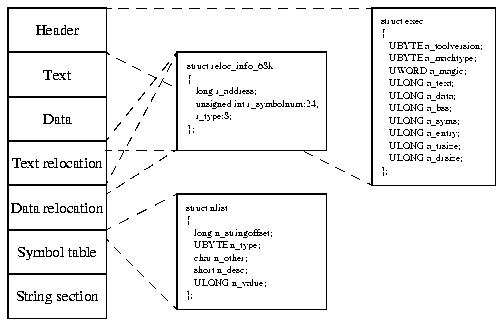
Usually all programs have a number of absolute references to other parts of code or data areas. What kind of references, where they are, and what is referenced is saved into the object file. Normally the linker uses this information when linking two object files together. Correcting the references is called relocation. The symbol table part is needed to resolve and fix references between separately compiled program sections.
Xld can be used to link together object files so that a new object file is produced. This is called incremental linking and it preserves all relocation and symbol information that is needed in the final linking phase. This means that xld can be used to collect all relevant object files into an almost ready, incrementally linked object file. On the other hand, in incremental linking xld will not complain if some external symbols remain unresolved. It assumes that they will be defined in other object files and resolved by the time the executable is created. This is of course correct behaviour, but it must be taken care of. Also, common uninitialized data regions are not allocated before the final linking phase. So, simply put, there may remain unresolved external references in an incrementally linked file.
Xlink reads an a.out format incremental link file (or an object file), goes through the relocation information and allocates all uninitialized common data regions while also resolving any references to them. This is normally done by xld during the final linking phase. In addition, offset values for data relocations are changed to be relative to the data segment start address instead of the text segment start address. This is because dos.library will allocate code, data and BSS areas separately, unlike Unix, which has code, data and BSS consecutively located in memory. However, this change has no effect in the executable file format itself. Also, Xlink changes the a_toolversion in the executable header to 68. Symbol information is removed to decrease the executable size.
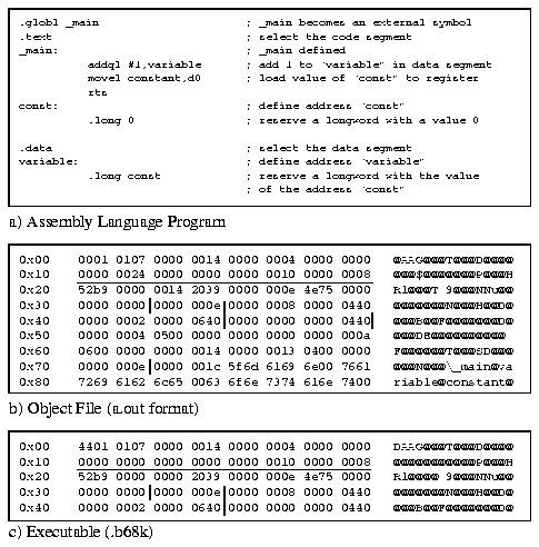
Figure 16 shows the source code, object file and the Xlink-linked final executable of a program that has some different relocations. Both object file and the executable have the executable header, code, data, code and data relocations. In addition the object file has a string section that names the symbols.
In addition to the linking itself Xlink can perform other tasks. You can generate raw files from executables. This is needed when you like to transfer a program into EPROM. In this case xld is first used to link the executable into a fixed address. Xlink strips away the a.out file header and symbol information, generating a file with only the program code and data. The relocation information is not needed, because the code does not need to be relocated.
You can also use Xlink to make linkable object files from raw data files. When you use a program to generate data used in the progam, it is not usually very convenient to import the data to a source code file each time the data changes, especially if there is lots of data. However, it is very convenient to use Xlink to generate a linkable file out of the data. You can then refer to the data with symbols, _<filename> and _<filename>_end. These symbols define the start and end addresses of the data, respectively. The data is considered non-changeable and is located in the program code segment.

Figure 17 shows how the BOAR executable is assembled using the programs in the development system.
Link libraries are provided to let the programmer use pre-programmed routines. A link library is a collection of object files which declare one or more external symbols. These symbols are usually routine access points. If effectively all a routine does is just call a corresponding system library routine, that routine is called "a stub."
If one of the symbols defined in a library object file is referenced by a program, that library object is added to the program. It is best to put each function into its own object file, because a whole library object is added even if only one of its symbols are referenced. This way code that is not used by the program is not included. On the other hand, this way the number of object files soon exceeds practical limits.
A reasonable compromise is to group routines that are usually all used if one of them is used. For example you should call the file close routine if you opened a file. Also, if you open a file, you probably read from it or write to it. So, you can put open, close, read and write stub routines into the same file.

The file in Figure 18 contains stubs for four routines. Each stub loads the library base into the appropriate address register, gets the parameters from stack and puts them into their proper registers, then calls the library routine. The appropriate negative offset value is used with the address register to call the right jump table entry.
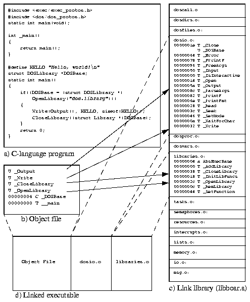
The program in Figure 19 a) refers to four system routines and defines two external symbols, _DOSBase and __main showed in b). During linking, these four unresolved references are found from the link library libboar.a and the objects are copied to the executable. Although only two symbols in both dosio.o and libraries.o are referenced, the whole object is copied. Also, dosio.o has an unresolved symbol _DOSBase, which must be, and is defined in the object file being linked. In short, an executable file is produced by taking the object file b) and the appropriate parts of the link library c).
Programmer's manuals contain documents describing the structure of the operating system and a detailed list of all available functions in exec.library and dos.library. Hypertext is a very convinient format for documentation, because it makes it very easy to locate detailed information. For example, structured function argument types can be studied by simply selecting the desired type in the function documentation, which gives the documentation about that type.
User's manuals contain documentation for the different tools (xtfpart, xilbitcat and xilscript) and a manual for the command line interface (shell).
/share/crosscomp/bin/xcc -nostdinc -I../include -I./ -ansi -Wall -pedantic -ffixed-a5 -fomit-frame-pointer -funsigned-char -O -c -o prg-example.o prg-example.c
xld -L../lib -L/share/crosscomp/lib -r -o prg-example ../lib/c.o prg-example.o -lansi -lboar -lgcc1
xlink prg-example
Outputting .b68k-format
Relocation possible
130 albert@isosotka Examples > x
^P to quit, ^U for BASE64 upload, ^T/^R for ymodem up/download
Connection established to sigx8.cs.tut.fi, port 9100
RAM: >
File to upload: prg-example.b68k
Sending using x/ymodem-chksum/crc16. Use ctrl-X's to cancel
Sending "prg-example.b68k"
CRC16-mode initialized
Sending block 4
Transfer successful. (1724 cps)
CRC16-mode initialized
Sending block 0
1 file received
RAM: > prg-example.b68k
Largest memory block: 5812008
Total free memory : 5853824
RAM: > ls -l
------drwedrwedrwe 0 22335 Today 02:00 dummy.bit
------drwedrwedrwe 0 89071 Today 02:01 g.bit
------drwedrwedrwe 0 4835 01-Jan-78 01:00 main.out
------drwedrwedrwe 0 22337 Today 02:00 mx_dual.bit
------drwedrwedrwe 0 3448 01-Jan-78 01:36 prg-example.b68k
------drwedrwedrwe 0 152 01-Jan-78 22:48 rpe_data.in
RAM: > info
Mounted disks:
Unit Size Used Free Full BlkSz Name
ROM: 3.7M 3807 11553 24% 256 ROM
RAM: 138K 277 0 100% 512 RAM
Handlers:
SER:
RAM: >
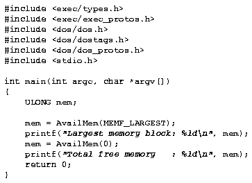
As can be seen from the above transcript, xcc, xld and xlink are used to create the executable program in the Unix system. The terminal program x is then used to connect to BOAR and upload the executable program. The program is then run, and it displays the memory size as expected. Listing the disk contents we see that some other files exist there also.
File hierarchies are implemented as handler processes, which listen to their message ports and service incoming requests. These requests normally come from dos.library, but an application program can also do direct requests. Dos.library only provides routines for synchronous file operations, but if necessary, applications can use asynchronous communication.
Dos.library can only be used by a process. A process is an extension to the task implemented by the exec.library, including such things as default input, output and error streams, local variables, the command search path and the current working directory. However, the scheduler makes no distinction between tasks and processes. Tasks and processes are scheduled in exactly the same way.
For example "RAM:c/sx" is a file named "sx" in the directory "c" on a disk named "RAM:". A filename "SER:serial.device/0/raw" tells the serial handler to open the stream to an exec device named "serial.device", unit 0 and start in "raw" mode.
If there is no handler name in the filename, it will be interpreted relative to the current working directory of the process. If the first character is a colon, the starting point will be the root directory of the handler. A full stop denotes the current directory, two full stops refer to the parent directory.
These preloaded segments can then be run either sychronously by RunCommand or asynchronously with CreateProc. RunCommand uses the current process to run the program, CreateProc creates a new process to run the program in. When the program exits, the segment list is unloaded.
A deferred (late-binding) assign type is available. Normally paths are evaluated immediately when an assign is created, but a deferred assign evaluates the path when that assign is first used. If at that time the path does not point to a valid directory, an error is returned, but the assign is not removed. After all, the path may become valid later.
Basic operations that stream-type handlers recognize are open, close, read, write, set mode, and wait for character. Streams that are not interactive, i.e. they represent stream-type storage media, may implement other operations also, like seek.
Two filesystem handlers were written for BOAR. One of them uses the available RAM to store the files. This is called ramdisk. Unfortunately RAM loses its contents when the system is reset. Another handler stores the data into a non-volatile media and is called romdisk.
Both these handlers are single-threaded. This means that they service one request at a time, and each request is returned before the processing of the next one is started. The message queue handles the synchronization and exclusion. The single-threaded handler is the sole owner of the filesystem structures.
Directories are implemented as simple linked lists of files and directories contained in that directory.
File ownership and protections are implemented by the handler. Each directory entry has a 32-bit permission field, a 16-bit owner identification number and a 16-bit group identification number. Four bits set the delete, execute, read and write permissions for the owner of the file. Four bits set the same permissions for any user with the same group identification number as the file specifies and four bits set the permissions for other users. One bit is used to mark script files for the shell.
Permissions define allowed operations for each user-file-directory combination. A directory may only be accessed if it has execute permission for the user. Files can be created if the directory also has write permission. Removing a file or directory needs delete permission. In addition, only empty directories can be deleted.
Ramdisk cannot be formatted, because the handler does not understand the corresponding request. Removing all files and directories is analogous to formatting ramdisk.
Directory hierarchy in romdisk is implemented as hash tables of lists [14]. Hash tables provide a way to find and retrieve keyed information fast and efficiently. In this case the key is calculated from the file name, and the file or directory in question may be found from the corresponding list.
Special attention is needed to design the logical structure of a disk, because EEPROM can be only programmed by turning one-bits into zero-bits. Only entire EEPROM pages can be erased, i.e. turning the bits into ones. Because there are only sixteen pages total, it is not reasonable to erase and reprogram a page whenever a disk block in it is changed. That would severely decrease the lifetime of the EEPROM chips and cause major delays whenever the disk is written to.
To be able to update the file lists, the list end marker cannot be zero, because that could not be changed. The end marker must be a bit pattern of all ones, which can be changed to any pointer. This directly applies to all pointer fields that must be updated.
The block size used by the handler is settable to any power of two when the disk is formatted. However, the minimum size is 256 bytes. This is enough to store one directory entry and a four-element hash table. For larger block sizes the hash table size is increased. When the disk is formatted, all available blocks are marked free. After allocating space for the allocation table itself, a boot block and the root directory of the disk, a new allocation table is written to the disk.
The boot block contains information about the disk, for example the block size used and where the allocation table bitmap blocks are. The boot block is located at the start of the media, in this case EEPROM. The root block and the bitmap blocks are normally in the middle. When a block for file data is needed, the allocation proceeds from the middle downwards, allocation of data management blocks proceeds from the middle upwards. If there is no space, allocation wraps to the other side. Figure 21 shows the algorithm.
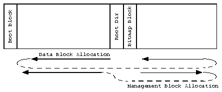
With EEPROM the allocation method is irrevelant, because access time does not depend on the location of the data. However, the handler was written to allow easy adaptation for other storage media. Buffering of blocks should still be arranged for e.g. hard disks to prevent disk read-write-head trashing. Also, the current allocation method unnecessarily spreads the management blocks of a file to a great distance from the file data blocks. It greatly depends on the relative size of the files and on the block size if it is better to use the same allocation method for both data and management blocks. Directory access, however, is faster if all management blocks are near each other.

Figure 22 shows how the blocks of one file may be distributed on the disk. Directory block holds the file name and other access information, extension blocks contain pointers to the data blocks, which hold the actual file data.
The hash key value calculated from the file name is used to locate the proper list to put the file or directory into. Entries can only be added to the end of the list, because already programmed pointers cannot be changed. For other types of media it is much faster to add newly created entries to the head of the chain. On the other hand, each list in the hash table becomes shorter if the block size is increased, because the handler can use larger hash tables.
When a file or directory is deleted, the entry type field is turned into all zeros. This deleted entry is then skipped by all routines that access the list and the entry does not show to the application programs. The space allocated by the file is not marked free, because of the EEPROM programming restrictions. Again, for other types of media, the directory entry and other blocks associated with the deleted entry can be immediately returned into use.
A special cleanup routine must be executed whenever the disk becomes full. This cleanup routine is not called automatically, because it more or less halts the system when reprogramming the EEPROM. The cleanup routine has to be initiated by the user, but can otherwise be run whenever necessary.
Because file locking depends on the block numbers of the directory entries, cleanup should not move the existing directory entries. This somewhat complicates the procedure. The cleanup proceeds in three stages. First the whole file hierarchy is checked and all used blocks are remembered. After this the whole disk is erased, i.e. all bits are turned into ones. In the third stage the block allocation bitmap is updated and all used blocks are programmed back into the EEPROM.
Because blocks are not moved, the cleanup is transparent to file and directory locking. Also, the cleanup has no impact on files opened for writing. Links to directory entries have to be changed when already deleted entries are removed. However, because the block numbers of the deleted directory entries are not used anywhere, programs that are scanning directory contents are also unaffected. This is because the structure used for directory scanning holds the block number of the current entry, not a pointer to the next entry. When a program asks for the next directory entry, the handler reads in the updated sector and uses the updated pointer to locate the next entry.
File ownership and protections are implemented similarly as for the ramdisk. Formatting of the disk is reserved for the disk owner.
If the user gives an exact command name, the shell either finds the command or it does not exist. However, locating the command to execute is not always this straightforward. The shell is given a list of directories from which to search for the commands. This list is called a command search path. When the user does not give a relative or absolute path for a command, the command search path is checked in order to locate the command. The first suitable file is then executed. The file is either an executable file or a script file. A number of internal commands are also incorporated into the shell and there is no need to try to locate them from the disk.
Command line editing and a history buffer for command lines exist. Because most of the users come from a Unix background, the command line editing was written to allow similar usage as in most Unix shells. Besides the normal editing keys, such as the cursor keys, delete and backspace, control-K can be used to kill the rest of the line. This deleted part can be yanked back with control-Y. The tabulator key performs filename or command completion, including the commands along the search path.
Command line editing is only used when the shell reads from an interactive stream. The current input stream can be a file, in which case the editing is turned off.
Internal commands include setting and clearing of aliases and local variables, file and directory manipulation and information commands.
Command output can be redirected into a file and input may be read from a file. Variables are expanded on the command line.
Internal commands include alias, cd, chmod, copy, ls, mkdir, path, rm, type. A full list of internal commands can be found from the shell manual in appendix C.
The first thing I discovered was that the intended memory mapping was impossible to implement. The MC68302 chip has four programmable chip selection pins, but they have their restrictions. Because the layout and routing of the system control board was almost completed, the change on that board could not be big. By exchanging the function of two chip select pins it was possible to fit everything into the address space of the processor with minimal amount of rerouting work.
Some other address decoding problems were discovered later, and most of the time it was only necessary to change some programmable array logic (PAL) equations to fix them. However, this was not possible when one needed address line was missing from one PAL chip. Fortunately there was another address decoder chip on the same board, which could be used to partly decode the address for the PAL.
The board was then manufactured and all the necessary components were soldered in, but when we were trying to run the operating system for the first time, no memory refresh cycles were present. The timer and co-processor were set up correctly. We finally found out that the socket for our MC68302 processor did not provide adequate contact between the socket and the chip. The timer output signal never got into the refresh trigger input pin. The socket was soldered out and the MC68302 was soldered directly onto the board. Memory refreshes started working just fine.
Apart from some errors in the software, the operating system seemed to work fine -- for a 100 ms or so. After that, seemingly from nowhere, a bus error was generated. The bus error vector was fetched, but another bus fault was generated during that fetch. After this the system just sat there doing nothing, because a double-bus-fault halts the processor.
Again, it took a lot of time to locate the problem. It was the Ethernet controller, which drove the data acknowledge line high. The processor's chip select logic then tried to pull that line low, without success. After 128 clock cycles a bus error was generated, but the vector fetch naturally failed because the data acknowledge was again pulled into two directions. Fortunately the processor generates all data acknowledge signals in the system. The data acknowledge signal could just be routed through an unused port in one PAL chip, separating the Ethernet controller and the processor. (The reason for this behaviour was found out later, the fix did not cure the reason, just the consequence.)
Small changes needed to be done to the dataflow test vector memories, because two data bus buffers were activated simultaneously when the processor read from those memories. However, due to too few control signals in the buffers, the test vector memory which feeds test vectors to the dataflow input can only be written. Obviously, test vectors saved to the output memory need to be read and now also can be read.
A similar problem was found from FPGA configuration memories, and only serial configuration by the processor is possible. Fortunately, this is not a problem, because configuring FPGAs serially is equally fast, or even faster than letting the chips configure themselves, because the configuration stream does not need to be copied to the configuration memory.
By this time both the original hardware implementors had left the project. Because I was by now very familiar with the system and not a total novice concerning hardware this was not a big problem. I continued testing the system and when a problem occurred, I used a logic analyzer to locate the problem, and then tried to devise a cure.
A set of surprises surfaced when it was time to test the ethernet controller. I found out that three signals on the chip were not connected. Unfortunately they should have been connected to the supply voltage for proper operation. One of the unconnected signals was also the cause for the 100 ms bug described earlier. That day I learnt how to solder 1 mm wide traces. Later I found out that I had accidentally unsoldered one of the chip's legs in the process. Soldering it back took less than a minute, but I spent more than two hours wondering why the watchdog counter did not work.
Tying those three signals to the supply voltage allowed me to write to the ethernet controller's registers, but reading them resulted in garbage bits. I found out why. One of two data buffers is activated depending on which part of the memory is accessed. Parts of the memory are connected through one buffer and the rest through the other buffer. However, the ethernet controller is directly connected to the processor's data bus, not through either of these buffers. Every time an ethernet controller register was read, the other buffer put garbage data into the bus, masking the real data coming from the ethernet controller. This was cured by changing the PAL which controls the data buffers. One added wire was needed to indicate when the ethernet controller was accessed.
By now I had also learnt three different PAL programming languages. ABEL was originally used in the project, but it needed an ABEL compiler, which was not easily available to me. Our PAL/EPROM programmer system used a language called PLDASM and could read existing PAL chips and convert their contents to PLDASM format. However, it surprisingly failed to compile a PLDASM file it had itself unassembled. PALASM was the third PAL programming language, and PALASM utilities also managed to compile the file.
Currently I have several thoughts about possible improvements that should be made before the next version is built. The first thing to do is to make the design more modular. The whole system should be split into several smaller subsystems that reside in different boards. Connections between these subsystems should be done using both mechanically and electrically high-quality connectors. In a modular system any error would have no effect on anything else than the board it is in. Connecting and disconnecting the boards would also become a less arduous task.
Handshaking lines from the processor to the FPGA part need to be added. Currently the FPGA part can see the processor's data, but it does not know when the data is valid nor when the data is intended for it. By adding handshaking signals test data can be directly written and read using the processor. If some address bits are also connected, FPGA designs that have a register-architecture can be directly tested using the processor. The same handshaking should be available to the clock FPGA. Also, test data memories can, and should be unified. It should be possible to use the whole memory area either for input test data or for output data or for both at the same time.
FPGA configuration memory could also be eliminated. Slave serial configuration by the processor is equally fast as configuration in master parallel mode, where one FPGA chip reads data from configuration memory and then serializes it into an internal configuration bit stream. The configuration data has to be in the processor memory anyway, and copying it to the configuration memory is an extra step that need not be done. Also, the number of chips that can be configured is limited because the configuration memory size is also limited. In slave serial configuration mode any number of chips can be configured as long as the configuration bitstream fits into the processor's memory. Originally the configuration memory was included so that all possible configuration possibilities would be available.
Only two SIMM slots are really needed for processor RAM. The total addressing capability of the MC68302 processor is 16 megabytes. Part of this needs to be reserved for other uses, such as other memory and peripherals. The practical maximum of 8 megabytes of RAM memory for the processor is easily achievable with two four-megabyte SIMMs. Smaller memory configurations (2 megabytes and 512 kilobytes) are also possible when using smaller memory modules.
To be able to get closer to the rated memory speed, DRAM logic needs a faster clock. Currently part of the DRAM speed is lost because the logic clock is the same as the MC68302 clock, which is only 20 MHz (50 ns). Because the processor does not have an instruction cache, memory speed directly affects its performance.
When MC68EN302 becomes available in smaller quantities, it would be a good choice to replace the basic MC68302. MC68EN302 includes an ethernet controller, thus making a separate ethernet controller unnecessary. This in turn makes it possible to remove a lot of the logic that was previously needed to provide control and buffering for two physical bus masters. (There are several logical bus masters inside MC68302, although there is only one physical bus master.)
When I started this project, I had already written a pre-emptive multitasking core for a Philips 68070 card during an embedded systems course. This previous project gave me an idea of what to expect and also what went wrong that time. Almost all of the code could be transferred directly, which reduced the possibility of errors. However, I had been coding without the hardware for two and a half months, and when the hardware arrived, some bugs had of course slipped into the code. It took a couple of weeks full of long working days and many more EPROM programming sessions to get the system working enough to begin work on the upper software layers. However, most of this time it was the hardware that was not working, not the software.
For BOAR I revised the list node structure to include name pointers. I made a big mistake during the 68070 project by leaving out the name pointer and decided not to do that twice. When nodes have a name, it is possible to search for them by name whether they are libraries, devices, tasks, public ports or public semaphores. Application programs can also benefit from using named nodes. For example hash tables for entries that are accessed by name are very easy to create using the system routines.
I also changed from a single task queue to a prioritized task ready queue and a wait queue, which made the scheduler much simpler, but also made the signalling function more complicated. If a task is awakened by signalling, it has to be moved from the wait queue to the ready queue. Previously only the task state had to be changed, now that part of the code had to be protected from interrupts, because it also had to be possible to call the signalling function from inside interrupt servers.
I had also written a fair amount of software, including a shell, for AmigaOS. It was fairly easy to use the code from that shell to develop a shell for BOAR. A serial handler I had written needed some minor modifications, but worked almost perfectly on the first try. A better buffering method was added later. The new version uses a circular buffer to avoid unnecessary copying of data. Unfortunately serial data is still copied upto three times, but this cannot be avoided if we want type-ahead and line editing while the application itself is busy.
One mistake I duplicated from AmigaOS was that I did not include a reference count in public message ports. Without a counter it is not possible to know whether any process has a reference to the port or not. This in turn makes it unwise and dangerous to remove public message ports. By the time I remembered this, a version of the software had already been delivered to a client and changing the message port structure would have meant recompiling everything. I decided against adding a reference count, because you can either not remove a public message port, or use public semaphores instead.

A simple terminal program shown in Figure 24 only needs to read the keyboard and send the characters to BOAR and simultaneously read the BOAR output and print that on the screen. A separate thread can handle input from the keyboard and another handles the output.
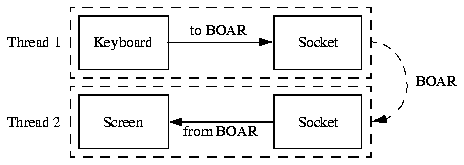
To transfer program code and other data across, some kind of a transfer protocol is needed. The first transfer format that the BOAR monitor program understood was a simple BASE64-code. To be exact, this was not a transfer protocol at all, because it did not provide any means of error checking, timeout features nor recovery from errors. But it was a start and almost satisfactorily got the data across.
In this transfer system the terminal program just told the name of the file to transfer and how many bytes to expect. If a byte was lost, the BOAR monitor program would wait for the last byte even when the terminal program had sent all of the bytes. The only way to recover from this was to type some valid BASE64 alphabets by hand and then retry the file send, hoping that it would work the second time. Even worse, there was no way to find out if characters changed during transmission.
After locating the document that describes the Ymodem protocol it was a fairly straightforward task to make the same evolution to the Xmodem transfer programs I had coded ten years earlier. The results were programs called rb and sb (receive batch, send batch). The same transfer and receive routines had to be coded into the terminal program, too.
When the serial port is set to 38400 bits per second (bps), the Ymodem implementation with a 1024-byte block-size achieves the transfer speed of 3000-3300 bytes per second, out of the top theoretical maximum of 3840 bytes per second. That maximum also does not include the protocol overhead. It should be noted that because Ymodem, unlike Zmodem, is not a streaming protocol, it has to stop after each packet and wait for an acknowledgement. The normally achieved 3000 bytes per second can be considered a fairly good transfer speed for this protocol.
Ethernet connection provides much better throughput compared to the serial port and also allows multiple connections simultaneously. When using a handler that implements a network filesystem (NFS) client, emulation data, programs and scripts can all reside in the host system. It is no longer necessary to first transfer configuration and test scripts to BOAR. A file in the host system can be accessed as if it were just another file in BOAR, the filesystem takes care of getting the data across. On the other hand, ethernet needs many levels of software to work.
When the ethernet connection is added, it is also necessary to include user identification into the system. Different users are already supported by the operating system. Each task has a user identification number and filesystems do implement protections. A user is not able to read other user's files, unless the protections allow it. Three things need to be added: user database, utilities to add and remove users (usage of these utilities is resticted to administrators only), and identification of the user before allowing him to start using the system.
When creating configurations for BOAR, the first input file contains the configuration for the master Xilinx, the second for the first dataflow Xilinx and so on. Xilbitcat separates the configuration parts from the input files, merges them and creates an output file, which contains a single configuration stream. This can be done on the host system or in BOAR, whichever seems more convenient.
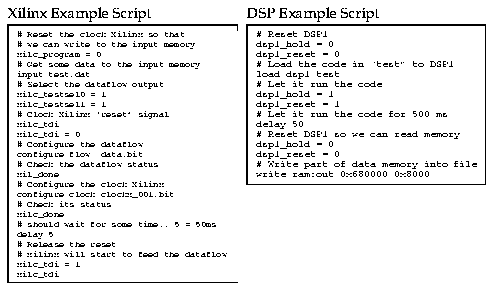
The example scripts demonstrate the simplicity of the script language. Signal states can be displayed by giving the signal name and set by assigning a state to a signal. FPGA chips are configured and DSP code is loaded with a single command.

Because BOAR has four Xilinx FPGA chips, big designs must be divided between them. This has to be done by hand, because appropriate tools are not available. The designer then needs to, not only keep track of the input and output signals of the system, but also the routing of signals from one chip into another. The possibility of errors increase if the designer is required to handle all this without any help.
Partitioning software called xtfpart was written to allow the designer to concentrate on the actual design of the system. The BOAR emulation part with the four Xilinx FPGA chips may be handled as one big logic chip. A set of predefined signal names are understood by xtfpart and they are directly mapped into the right input or output pins. Also, routing between different chips is automatically done by xtfpart. The designer can also influence the mapping of logic blocks and fix any of the blocks to a specific chip.
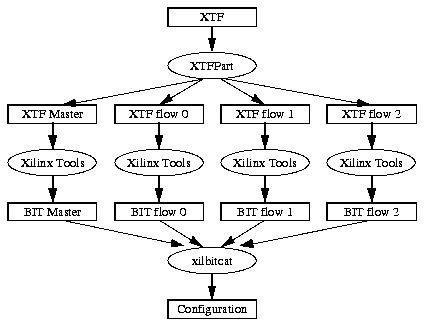
As described in Figure 27, Xtfpart reads one design file and generates four separate designs. These design files are then further processed with the Xilinx tools to generate configurations, xilbitcat is used to merge the configurations and xilscript may be used to test the result.
.
Table 1: XTFPart flow
----------------------------------------------------------------------------
#  Operation     Description
----------------------------------------------------------------------------
1  Input file    Read in XTF-file and generate a structured representation
2  Check nets    Check that all nets are connected and have driving signals
3  Check depths  Calculate lengths of signal paths
4  Bind EXTs     Bind external and fixed symbols into appropriate chips
5  Clusterize    Group symbols - minimize connections between groups
6  Partition     Put each symbol group into one of the Xilinx FPGA chips
7  Optimize      Symbols that connect into different chips are checked/moved
8  Route         Route signals between chips using the best connection
9  Output        Output four XTF-format files
----------------------------------------------------------------------------
Table 1 lists the different operations Xtfpart performs when partitioning a design.
Xtfpart reads Xilinx-preprocessed XNF-format files named XTF. All macro symbols have already been replaced by basic logic symbols, and hierarchy is hidden so that the whole design resides in one file. The original design hierarchy is not totally lost, because it is partly preserved in the hierarchical naming of symbols and signals. An XNF grammar was written, and a parser that understands that grammar is used to read an input file and generate a structured internal representation of the design. All processing then deals with this internal structure.
The XNF file format is symbol-oriented. For each symbol pin there is a signal name that defines the signal net that the pin is connected to. The connecting signal nets themselves are not saved separately. While reading the file, a data structure describing these signal nets is created. This way it is easy and, most importantly, fast to find all symbols connected to each net.
When the whole input file has been read, all nets are checked. Each net should have at least two pins connected to it. Also, there should be one, and only one driving signal in each net. In the next phase the length of each asynchronous signal path is calculated. A latch or a clocked buffer of some kind separates these supernets.
External symbols are next located into the right chips. The designer need not worry about the output and input pin names. He can use logical names that describe the intended function of the pin instead. Logical names are automatically converted into chip-pin combinations and assigned into their proper places. Global clock buffers and other special symbols are copied so that each physical chip gets them and can function normally.
The partitioning heuristics is the most important part in Xtfpart. It has to decide which symbol goes to which chip, and at the same time take care that all signals that cross physical chips can be routed, and that the routing between chips cause as little impact on the maximum speed of the design as possible. Shorter supernets are favored in interchip routing, because they should tolerate the additional delay caused by the routing outside the chip.
This kind of heuristic algorithm is easy to create when small designs are concerned. Bigger designs usually have more signals, and more signals have to be routed between chips. Because of this it is imperative that designs are first clusterized, minimizing the number of signal connections between clusters. Feedback signals further complicate the procedure by creating loops that somehow have to be resolved.
When the final partitioning is reached, nets that connect pins in different chips are routed. Different routing connections are used depending on which chips are involved. For adjacent dataflow chips dataflow lines that are not occupied can be used. Otherwise control and peripheral bus signals are used for routing. Output and input buffers and other symbols that are needed are automatically added to the relevant chips. When routing is completed, four XTF files are output, containing the partitioning results.
From the software point of view the goal was to create a light-weight, flexible and easily extensible operating system, and application programs that would allow using the system without any programming knowledge. One part of this goal was easy integration with simulation environments.
A pre-emptive multitasking operating system was implemented for BOAR. Also, all the necessary device drivers, filesystems and application programs to use the emulation hardware were written. Work to produce automatic partitioning software was started.
The implemented operating system proved to be very stable. Also, according to the system's users, the application programs are easy to use and thus fill their intended functions perfectly. On the other hand, further work is needed with the automatic partitioning software. The problem proved to be too complicated to be completed without further research in the area.
Testing of macro library components has been one of the uses for BOAR [1, 10]. Integration into simulation environment was also successful when my co-workers linked BOAR to the Ptolemy co-simulation environment.
[2] V. Köppä, "An Advanced Real-Time Prototyping Environment for
Embedded DSP Systems", Master of Science Thesis, Tampere Univer-
sity of Technology, Finland, To be published in 1996
[3] J. Oksala, "Design and Implementation of High Performance DSP-
ASIC Emulation Tool", Master of Science Thesis, Tampere University
of Technology, Finland, October 1994
[4] T. E. Bihari, P. Gopinath, "Object-Oriented Real-Time Systems:
Concepts and Examples", Computer, December 1992, pp. 25-32
[5] R. B. Bunt, "Scheduling Techniques for Operating Systems",
Computer, October 1976, pp. 10-17
[6] Dittrich, Gelfand and Schemmel, Amiga System Programmer's
Guide, Abacus, 1988
[7] G. R. Gircys: "Understanding and using COFF", O'Reilly & Associ-
ates, Inc., 1990
[8] S. Guccione, "List of FPGA-based Computing Machines",
http://www.io.com/~guccione/HW_list.html
[9] I. Haikala and H. Järvinen, Käyttöjärjestelmät, Modeemi RY, 1994
[10] H. Hakkarainen and J. Isoaho, "VHDL Macro Library Testing Using
BOAR Emulation Tool", Proc. of IEEE 8th International ASIC Conference
and Exhibit, Austin, TX, September 1995, pp. 105-108.
[11] J.Isoaho, "DSP System Development and Optimization with Field
Programmable Gate Arrays", Doctor of Technology Thesis, Tampere
University of Technology, Finland, 1994
[12] J. Isoaho, V. Köppä, J. Oksala and P. Ojala, "BOAR: An Advanced
HW/SW Coemulation Environment for DSP System Development",
Submitted to Microprocessors and Microsystems, 1994
[13] B. W. Kernighan, D. M. Ritchie, The C Programming Language,
Second Edition, Prentice Hall, 1988
[14] T. G. Lewis and C. R. Cook, "Hashing for Dynamic and Static Internal
Tables", In Computer, October 1988
[15] H. L. Owen, U. R. Kahn and J. L. A. Hughes, "FPGA based ASIC
Hardware Emulator Architectures", In 3rd International Workshop on
Field Programmable Logic and Applications, September 1993
[16] J. A. Stankovic, "Misconceptions About Real-Time Computing",
Computer, October 1988, pp. 10-19
[17] W. Zhao, K. Ramamritham, and J. Stankovic, "Scheduling Tasks With
Resource Requirements in Hard Real-Time Systems", IEEE Transac-
tions in Software Engineering, May 1987, pp. 564-576
[18] The Programmable Logic Data Book, Xilinx, 1994
[19] TMS320C5x User's Guide, Texas Instruments, January 1993
[20] MC68302 - Integrated Multiprotocol Processor User's Manual,
Motorola, 1991
[21] Flash Memory Products Data Book, Advanced Micro Devices, 1992
[22] Local Area Network Databook, National Semiconductor, 1992 Edition
[23] The AmigaDOS Manual, 2nd Edition, Bantam Books Inc., February
1987
[24] TMS320 Fixed-Point DSP Assembly Language Tools User's Guide,
Texas Instruments, December 1991
[25] M68000 Family Reference, Motorola, 1988
A exec.library manual
B dos.library manual
C shell manual
D xtfpart manual
E xilbitcat manual
F xilscript manual
G nil.c - an example handler